Join us for Beyond the Bomb: Stories of the Atomic Age
An event by the Manhattan Project National Historical Park, in partnership with Oak Ridge Associated Universities (ORAU)
Join the MPNHP and ORAU for a free public program titled “Beyond the Bomb: Stories of the Atomic Age” on Thursday, February 12, 2026 or March 24, 2026 at 2 pm EST. Utilizing the rich history and museum collection of the ORAU Museum of Radiation and Radioactivity, this program will dive into atomic culture and innovations in medicine sparked by the Manhattan Project and expanded during the atomic age. Participants will have the unique opportunity to explore the Museum of Radiation and Radioactivity, not regularly open to the public.
More information is available on the NPS website.
Visiting the Museum
Please note that visits to view a selection of items in the collection are by appointment only.
To schedule an appointment, please visit our visitor page for more information.
-
Museum Directory
Links to different categories of items in the collection
-
Museum Library
Publications and videos relating to the history of the radiological sciences, biographies and oral histories
-
Radiation Basics
General information about radiation
Featured Collections
The Oak Ridge Associated Universities (ORAU) Museum of Radiation and Radioactivity chronicles the scientific and commercial history of radioactivity and radiation. It has been deemed the official repository for historical radiological instruments by the Health Physics Society, and the Society has been generous in its financial support for the purchase of items.
The collection is the property of the not-for-profit ORAU Foundation, and it is located at the Pollard Center in Oak Ridge, Tennessee. Unless noted otherwise, this website only features items actually in the collection. If you have any technical or historically-related questions about the collection contact Dr. Paul Frame via email. Please do not ask about an appraisal—we do not attribute monetary values to items. All other inquiries can be directed to communications@orau.org.

Measuring radiation exposure then and now
In the ORAU Museum of Radiation and Radioactivity, you will find hundreds of items that chronicle the history and commercialization of radiation and radioactivity. The collection includes a lot of dosimeters: film dosimeters, pocket dosimeters, thermoluminescent dosimeters, you-name-it-we-probably-got-it-dosimeters! Take a look at what these gadgets do and how they’ve been used through the years.

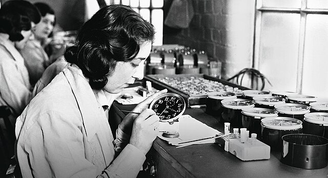
Radium Girls: The health scandal of radium dial painters in the 1920s and 1930s
By the mid-1920s and into the 1930s, a rash of radium-related illnesses began to emerge including hundreds of instances of severe anemia, radiation poisoning, bone fractures and necrosis of the jaw, a condition that came to be known as “radium jaw.” The common denominator in these cases: the sick had worked as radium dial painters.

What is a shoe-fitting fluoroscope?
Discover some fun facts about the shoe-fitting fluoroscope at ORAU’s Museum of Radiation and Radioactivity, such as who all claims to have invented the machine.

Oak Ridger: ORAU Museum of Radiation and Radioactivity—a most unique collection
Oak Ridge Historian D. Ray Smith discusses the impact of the ORAU Museum of Radiation and Radioactivity in his Historically Speaking column. The museum exists to chronicle the scientific and commercial history of radioactivity and radiation. While it is used for training and research purposes and not intended for public access, the museum's website has developed a much larger on audience due to the online descriptions and informative stories regarding an item's history.
Pop culture in the atomic age
Join Paul Frame, Ph.D., a retired health physicist and trainer at ORAU, as he shares a sampling of pop culture items and their backgrounds. Frame started the collection in the 1980s when he discovered X-ray tubes and other items in a cabinet. Over time, the collection has grown to include hundreds of items, many of them donated or purchased by either the Health Physics Society or the non-profit ORAU Foundation.

Radiation Safety & Health Physics Training Courses
Since 1948, ORAU has instructed more than 30,000 scientists, physicians, engineers, educators, regulators, and personnel in a variety of radiation safety and health physics courses through its Professional Training Programs (PTP). ORAU's PTP conducts a wide variety of online and in-person health physics and radiation safety training courses, including our noteworthy, five-week Applied Health Physics course and multiple one-week offerings.


