Electrometers
Lindemann/Torsion Electrometers
Lindemann Electrometers
Paul Frame, Oak Ridge Associated Universities
 Developed by Frederick Lindemann (Phil. Mag. 47: 577; 1924) for use with the photoelectric cells employed to measure the light from stars. It soon became a popular alternative to the standard quadrant electrometer as a means to measure current from ion chambers. Its virtues include its small size, relative ease of use, and the fact that it can operate in any orientation.
The Lindemann electrometer is essentially a quadrant electrometer. Each quadrant consists of a 1 x 1.5 cm flat plate with a 2 mm slot cut across it.
The movable component of the electrometer consists of a 1 cm long metal-coated glass fiber attached in the middle to a taut torsion fiber (a 1.4 cm long metal coated quartz fiber).
Two of the quadrants are mounted in the same plane on one side of the torsion fiber while the other two are mounted in the same plane on the other side of the fiber and needle. The electrical connections are the same as those of any quadrant electrometer but the applied potential is less (i.e., under 100 V).
When the fiber swings, one end moves into the slot cut in one quadrant while the other end moves into the slot of the diagonally opposite quadrant.
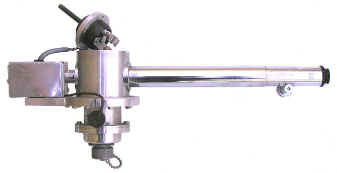
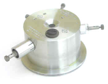
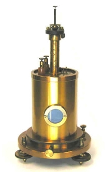
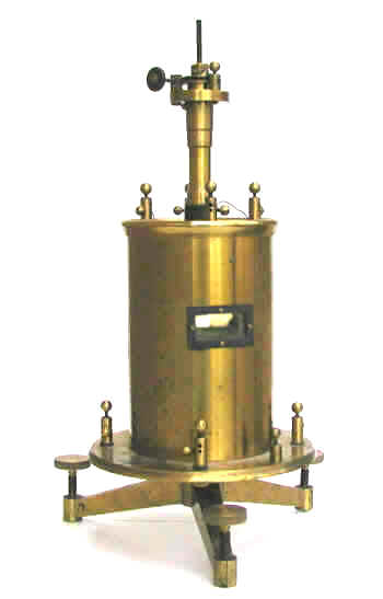
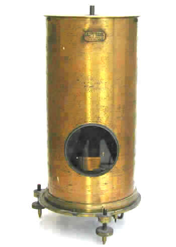
 The entire apparatus is housed inside a cylindrical aluminum or brass case. A circular glass window is located on each end of the case—one window allows light in and the other permits observation of the needle with a microscope. The voltage sensitivity, i.e., the fiber’s movement per unit voltage, is about 0.76 mm per volt. When the scale as viewed through the microscope, this translates to about 500 divisions per volt. The Lindemann electrometer is also capable of measuring currents in the 10-10 to 10-14 amperes.
-
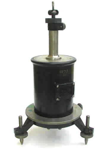
Chalk River Electrometer Chalk River Electrometer
-
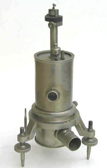
Lindemann-Ryerson Electrometer Lindemann-Ryerson Electrometer
-
Victor Hess's Lindemann Electrometer Victor Hess's Lindemann Electrometer
Quadrant Electrometers
Quadrant Electrometers
Paul Frame, Oak Ridge Associated Universities
The primary function of an electrometer is to measure an electrical potential (volts) or charge (coulombs)—charge and electric potential are directly related. By measuring the change in the accumulated charge over time, the current (amperes) can also be determined. One ampere is equivalent to one coulomb per second.
The basic quadrant electrometer was developed by Lord Kelvin (William Thomson) in the 1860s. The earliest versions were usually housed inside a “bird cage” or box. The bird cage electrometers got their name from the Faraday cage that was used to protect the instrument from stray electrostatic charges. In some cases, a glass bell jar protected them from the air currents which could affect their operation. The other common approach was to house the electometer inside a wooden box, the front of which was made of glass.
However, it wasn’t until the development of the Dolezalek quadrant electrometer in 1896 that a device was available with the sensitivity needed to measure the very small currents (picoamps) associated with the ionization chambers used to measure radioactive samples. Among other things, the Dolezalek electrometer and its later derivations protected the quadrants inside a cylindrical metal housing that had one or possibly two small glass windows.
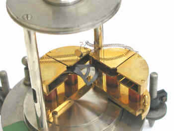
Quadrant electrometers could be operated in a number of ways but the most common method was to measure the rate of deflection of the electrometer’s vane (aka needle) suspended by a fine wire or fiber.
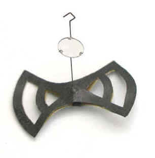
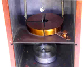
The potential being measured caused a butterfly-shaped vane (ca. 1 – 3” across) to turn. The magnitude of this deflection was related to the potential (or charge). The rate of the deflection was related to the current. The early electrometers used vanes that were solid metal and relatively heavy. In contrast, the vane of the Dolezalek electrometer was very thin and light—it was sometimes made of aluminum, sometimes of metal-coated paper. One end of a short rigid wire was connected to the middle of the vane while the other end of the wire had a small hook. The backside of a tiny mirror (a few mm in diameter) was attached roughly half way up the wire. The hook was connected to the end of a thin flexible wire or fiber so that the vane and mirror were suspended in air and free to rotate.
The vane itself was inside, but not in physical contact with, a metal “pill box” shaped device consisting of four quadrants. In the photo on the left, the quadrants have been opened up so that the vane is visible.
Each quadrant was electrically connected to the quadrant diagonally opposite it so that they had the same charge. One pair of quadrants had a positive charge and the other pair had a negative charge. The electrical charge on the vane caused it to take up a particular orientation within the quadrants. If the potential difference between the vane and the quadrants changed (e.g., due to current from the ion chamber), the vane and the mirror would rotate.
Prior to the measurement, the system was adjusted (mechanically and electrically) so that the vane was positioned inside the quadrants as shown in the accompanying figure. Half of each lobe of the vane was inside one quadrant while the other half was inside the adjacent quadrant.
To determine the position of the vane, a beam of light was shone through the window in the electrometer case so that it reflected off the mirror onto a scale usually positioned one meter away. As the current from the ion chamber changed the potential difference between the vane and the quadrants, the vane rotated and the reflected beam of light moved across the scale. The time required to move across a specified number of divisions on the scale could be related to the activity of the sample by calibration with a known source. In some cases, a calibration wasn’t necessary, only the relative rates of deflection under different experimental conditions might have been of interest.
Early Quadrant Electrometers
Note that the quadrant electrometers of the 1800s did not provide the sensitivity or the reliability that was required for radioactive work.
The early bird cage and box-like quadrant electrometers maintained the vane at a constant potential while the potential/charge being measured was applied to one pair of quadrants. The other pair of quadrants was grounded. The mechanism employed to maintain the potential on the vane was somewhat cumbersome: a wire was suspended beneath the vane so that the free end at the bottom (usually attached to some sort of weight) was immersed in a sulfuric acid solution. The sulfuric acid was contained inside a Leyden jar to which a charge had been applied. A Leyden jar, actually an early form of capacitor, is simply a glass jar, the bottom portion of which is lined on the inside and outside with metal foil. The sulfuric acid provided the electrical connection between the foil on the inside of the jar and the wire connected to the electrometer vane.
Dolezalek Electrometer
The Dolezalek electrometer, invented by the Hungarian, Friedrich Dolezalek (1873-1920), represented a significant improvement over earlier versions of quadrant electrometers by virtue of its increased sensitivity. It was invented in the same year that radioactivity was discovered (1896) and it quickly became a favorite of those investigating radioactive substances (e.g., Ernest Rutherford). Dolezalek spent most of his career in Germany and his research spanned a variety of fields: physics, chemistry, and electrical engineering.
The Dolezalek quadrant electrometer differs from previous designs in several respects:
- The vane is lighter. It was usually made of paper coated with a thin layer of metal (e.g., silver) although thin aluminum was sometimes used. Older vanes were solid metal.
- The quadrants are smaller.
- The mirror and vane were suspended by a metal coated quartz fiber rather than a phosphor-bronze strip.
- The Leyden jar beneath the quadrants has been eliminated.
The following diagram shows how a Dolezalek electrometer and an ionization chamber might have been configured to measure the activity of a radioactive substance. In this example a fixed potential (e.g., 100-200 volts) is maintained between one pair of quadrants (grounded) and the vane. The charge collected by the ionization chamber accumulated on the other pair of quadrants.
Major Types of 20th Century Quadrant Electrometers
- Dolezalek
- Compton - a variant of the Dolezalek electrometer. The major difference being that the Compton electrometer permitted a mechanical adjustment of the position of one of the quadrants.
- Hoffman - the most sensitive of the quadrant electrometers. Actually, it was a binant (rather than quadrant) electrometer that used a vane with a single lobe. It employed heat sinks to reduce thermally generated air currents that could affect the vane and it was partially evacuated so that it operated at reduced pressure (a few millimeters of mercury).
-
Cambridge Dolezalek Electrometer Cambridge Dolezalek Electrometer
-
Dolezalek Electrometer Dolezalek Electrometer
-
Dolezalek Electrometer Dolezalek Electrometer
-
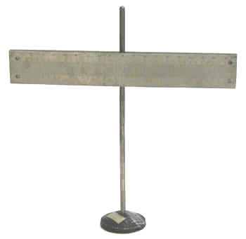
Galvanometer Scale Galvanometer Scale
-
Griffin & Tatlock Quadrant Electrometer Griffin & Tatlock Quadrant Electrometer
-
Harris Quadrant Electrometer Harris Quadrant Electrometer
-
Large Dolezalek Electrometer Large Dolezalek Electrometer
-
W.G. Pye & Co. Dolezalek Electrometer W.G. Pye & Co. Dolezalek Electrometer
String Electrometers
String Electrometers
Paul Frame, Oak Ridge Associated Universities
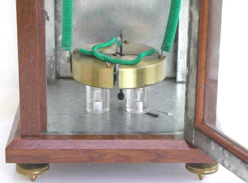
String electrometers employ a charged fiber or wire suspended in an electric field. By measuring the deflection of the fiber, usually with a microscope, the collected charge on the fiber can be measured. In almost all cases, the fiber is attached at one end to a post and at the other end to a flexible quartz bow which keeps the fiber taut.
While string electrometers have usually been employed to measure the collected charge from ion chambers, they were also used with Geiger counters. Pulses from a Geiger counter produce “kicks” in the fiber and the number of kicks can be related to the intensity of the radiation.
In general, string electrometers are portable and easy to set up. Perhaps their major disadvantage is the fact that their response is not linear.
The two major types are the Wulf electrometer, and what we will call a generic string electrometer, for lack of a better term.
Wulf Electrometer
The Wulf electrometer, first described in 1914 (Phys. Zeitz. 15:250, 611), consists of a fine Wollaston (platinum) wire or a metal-coated quartz fiber suspended between two plates. The wire/fiber is attached to an adjustable post at the top and a quartz fiber bow at the bottom. The bow ensures that the wire/fiber is kept taut. The plates, also adjustable, are approximately 1 cm apart. A potential of 100 volts or so is maintained between the plates, while the charge being measured is applied to the fiber.
Generic String Electrometer
This particular type of electrometer was popular because of its simplicity. In fact, it is so simple that it blurs the distinction between an electrometer and an electroscope.
A metal coated fiber or wire is attached at one end to a supporting post and at the other end to a quartz bow. As shown in the accompanying diagram, a brass rod is positioned parallel to, and about 5 mm away from, the fiber. The charge to be measured might be applied to the fiber while the brass rod is grounded. Alternatively, the fiber might be grounded while the charge is applied to the brass rod. In either case, the fiber is deflected towards the brass rod.
-
String Electrometer of Carl Braestrup String Electrometer of Carl Braestrup
-
String Electrometer of Carl Braestrup String Electrometer of Carl Braestrup