Chatlock's Gold-Leaf Electroscope by Griffin (early 1900s)
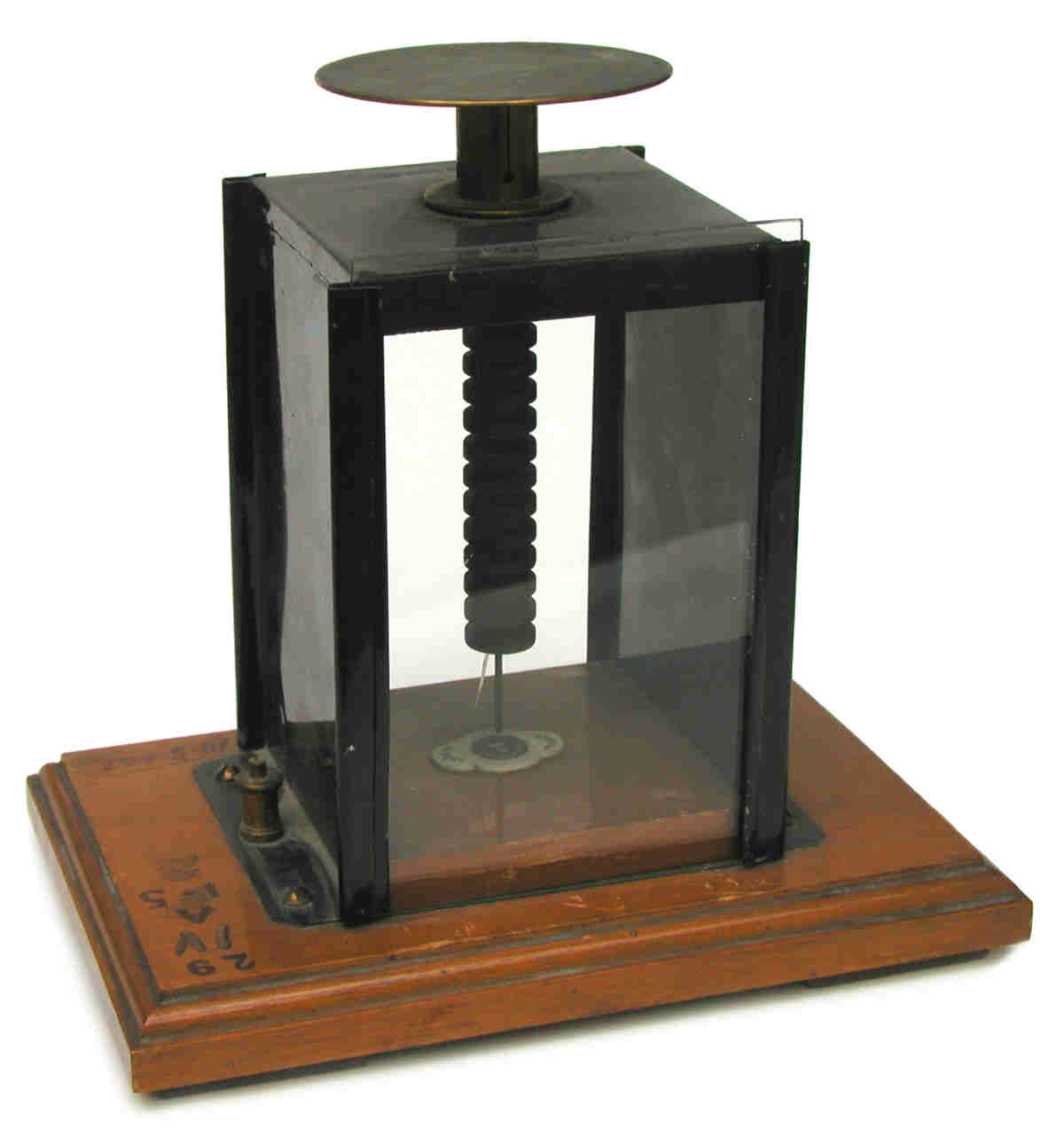
This is an early condensing electroscope that was intended for qualitative demonstrations of electrostatic phenomena. The single leaf, still attached at the bottom of the support (conductor) rod, is aluminum. A three-inch diameter brass condenser (Volta) plate is connected to the top of the rod. The front and back of the case are glass. The top, bottom and the two sides are sheet metal.
The defining characteristic of this instrument is the long-ribbed insulator (probably ebonite) that surrounds the support rod and separates the latter from the metal case. A nice explanation for how the insulator minimizes electrical leakage between the case and the rod-leaf-condenser is provide by Hadley (1913):
"Nearly all the leakage which may occur is conveyed along the surface of the insulating plug; the insulation is therefore improved by cutting V-shaped grooves on the surface of the plug, whereby the length of path traversed by any leakage is increased."
This tells us that the electroscope in the photo needs an adjustment. The distance from the top of the case to the top of the insulator should be the same as the distance to the bottom of the insulator. Just like the drawing.
In general, an electrophorus would be used to transfer a charge to the condenser.
Condensing Electroscopes and the Electrophorus
Condensing Electroscopes
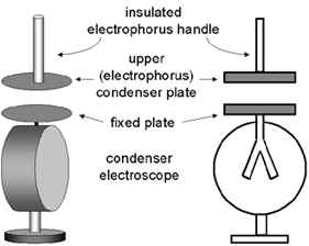
The defining feature of the condensing electroscope is the flat horizontal disk on top that is connected to the electroscope leaves (or leaf). This type of electroscope is primarily intended for electrostatic measurements but it can also be used to help identify the presence of radioactive material.
A condensing electroscope is designed to be charged with the disk of a device known as an electrophorus. The dimensions of this disk are the same as those of the fixed disk on top of the electroscope. The handle of the electrophorus disk is a glass (or other insulating material) rod projecting at right angles from the back side of the disk.
Charging the Electrophorus Disk
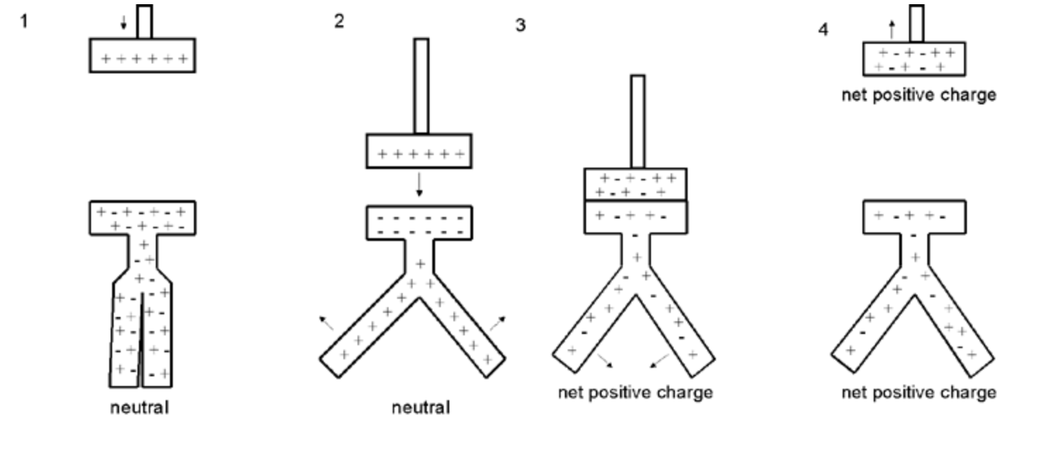
To begin, a charge must be generated on an insulating plate once known as the cake—this plate is considered part of the electrophorus. The charged plate (Figure 1) should have a smooth surface and be made from an insulating material (Teflon is perfect but plexiglass is a good choice). The plate is charged via friction by rubbing it with a material such as wool, silk or fur. Depending on the materials used, the resulting charge on the plate would be either negative (as shown here) or positive. The back (down) side of the insulating plate might, or might not, be in contact with a conductor that is grounded.
Next, the neutral electrophorus disk is brought in contact with the insulating plate. For the purpose of this discussion, the plate is assumed to have a negative charge. Although they are in contact, the plate does not transfer a charge to the disk because the plate is an insulator. Nevertheless, there is a spatial separation of the positive and negative charges in the disk: the negative charges (electrons) are repelled to the up side of the disk farthest away from the plate thus leaving a positive charge on the down side of the disk that is in contact with the charged plate (Figure 2).
Next, the disk is grounded, e.g., by touching the top of the disk with a finger. This causes the electrons to travel to ground leaving the disk with a net positive charge (Figure 3). Finally, the ground is removed and the electrophorus disk lifted away from the insulating plate (Figure 4).
Charging the Electroscope with the Electrophorus Disk by Conduction
There are two methods that can be used to charge the electroscope: by conduction and by induction.
To charge the electroscope by conduction, the electrophorus disk, which in this example has a positive charge, is brought into physical contact with the fixed disk on the electroscope Figure 3 below). Since electrons from the electroscope are drawn to electrophorus disk, the electroscope disk and leaf will be left with a net positive charge, the same charge as that on the electrophorus.
Charging the Electroscope with the Electrophorus Disk by Induction
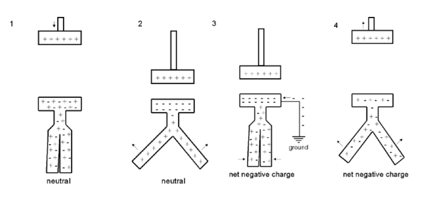
More control of the charge transferred to the electroscope can be obtained by charging it by induction in the following manner. The charged electrophorus disk is brought close to the fixed disk of the electroscope but the two are not allowed to touch. When the electrophorus disk is brought close, the electroscope leaves will separate. The reason is that the electrons are attracted to the upper surface of the electroscope disk, the side closest to the electrophorus, leaving the leaves with a positive charge. Since both leaves have the same charge, they separate (Figure 2). By moving the electrophorus disk away from or closer to the electroscope disk, the desired separation of the leaves can be obtained. Next the electroscope disk is grounded, e.g., by touching it. The electrons then travel to the disk leaving the electroscope with a net negative charge (Figure 3). The ground is removed (Figure 4) and the electrophorus lifted away from the electroscope leaving the electroscope with a net negative charge.
The maker's name is stamped on the top of the metal case: GRIFFIN, LONDON. A small plate on the inside the case, located just below the support rod, reads: Gramme Standard. Since it is my understanding that Griffin changed their name to Griffin & Tatlock sometime between 1910 and the late 1920s, it seems reasonable to date this instrument from 1900-1920.
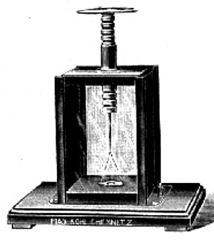
The figure below, taken from an undated Max Kohl catalog, shows a similar instrument. The catalog description reads:
"Electroscope, Chatlock's. Figure, with first-rate ebonite and air insulation, with aluminum leaf, also suitable for projection."
The same type of instrument is described as a gold leaf electroscope in a 1908 catalog published by Philip Harris & Co. Their detailed description follows:
"Comprising two narrow strips of gold leaf suspended from the lower end of a brass rod, at the top of which a metal disc is fixed. The wire [rod] is supported vertically by a a plug of insulating material (ebonite), and the leaves are protected from air currents by means of a case, the front and back of which are glass. The sides of the case are lined on the inside with strips of metal, which are earth connected. The insulating plug has V-shaped grooves on the surface to increase the length of the path of the leakage, which is conveyed along the surface of the insulating plug."
This is identified as "Chatlock's electroscope" because that is the name given to it in the Max Kohl catalogs. However, I have never seen this name employed anywhere else. Perhaps the design was associated in some way with A. P. Chatlock, a physics professor at University College (Bristol) in the late 1800s.
Size: ca 8" tall. The chamber is 5" high, 4" wide and 4" deep. The condenser (Volta) plate is ca. 3" in diameter. The wooden base is 5" x 8".
References
- Hadley, H.E. Magnetism and Electricity for Students. 1913.
- Max Kohl A.G. Chemnitz. Physical Apparatus. Price List No. 50. Vols. II and III. No date.
- Philip Harris & Co. Ltd. Explanatory Price List for Physical Instruments. 1908.