X-Ray and Gas Discharge Tubes
Gas Discharge Tubes - The Basics
Prior to Roentgen’s discovery of X-rays in 1895, many different types of gas discharge tubes were already in use (e.g., Geissler, Crookes, Hittorf, Lenard tubes). After the discovery, new types were developed that were specially designed to produce X-rays. Today, gas discharge X-ray tubes are commonly referred to as “cold cathode” tubes in order to distinguish them from “hot cathode” Coolidge X-ray tubes that employ a heated filament. But at the time they were being manufactured, they were simply known as X-ray tubes.
What these different tubes had in common was the fact that they were made of glass and were partially evacuated. Depending on the type of tube, the residual gas might or might not be air. Tubes designed for X-ray work usually contained air, although some (e.g., Snook tube) employed helium or hydrogen.
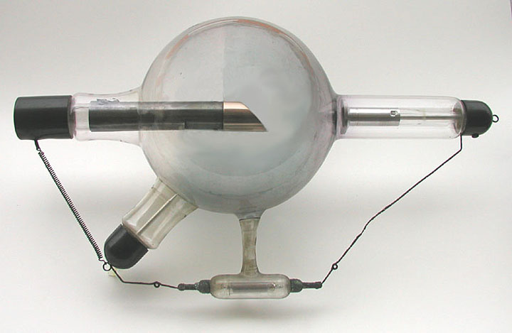
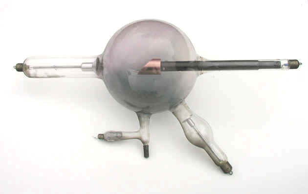
The configuration of these tubes varied, but there were always at least two electrodes (an anode and a cathode) that might, or might not, be located at opposite ends of tube. It was not unusual for X-ray tubes to have three electrodes: a negatively charged cathode, a positively charged anode, and what was known as an "anticathode." The latter (aka auxiliary anode) was usually given a positive charge, but it sometimes had no electrical charge at all. Tubes with both an anode and anticathode were often referred to as bi-anode tubes.
When a sufficient electric potential (high voltage) is applied across the tube's electrodes, a stream of electrons (aka cathode rays) travels through the gas from the cathode to the target. If the tube had an anticathode, it was the target. If the tube had no anticathode, the anode almost always served as the target. When the electrons struck the target, X-rays were emitted. The greater the current (on the order of a milliamp) supplied by the operator to the tube, the greater the intensity of the emitted X-rays. The higher the applied voltage, the higher the energy of the X-rays, and the more penetrating they became. For diagnostic imaging, more penetrating X-rays were preferred. For therapy, less penetrating X-rays were desired.
Several problems had to be overcome when designing the tubes. Perhaps the most important were an overheating of the target when the tube was under heavy use, short and long-term variability in the gas pressure, reversals in the direction of the current through the tube (inverse discharges), and electrical discharges that might puncture the glass wall of the tube.
Making the target more massive was the primary method used to prevent it from overheating. Adding one or two special appendages to the tube (regulators or regenerative devices) helped control the gas pressure inside the tube.
The primary ways that X-ray tubes differ involve the construction of the target and the design of the regulator.
Gas Discharge Tubes - Some Details
The physics of a gas discharge tube are complicated, and I only understand a little. Corrections and suggestions for improvement to the following discussion are welcome.
The application of even a relatively low potential between the anode and cathode will cause any free ions in the gas (electrons and positively charged gas molecules) to migrate to the electrodes. Free ions are always present due to interactions with of the gas cosmic rays and background gamma rays.
If the potential is sufficiently high, many of the electrons that accelerate towards the anode will pick up sufficient kinetic energy to cause a further ionization of the residual gas. The resulting positively charged gas ions (known as anode, canal or channel rays) accelerate towards the cathode, and the freed electrons (cathode rays) accelerate towards the target. Upon striking the cathode, some of the positively charged gas ions dislodge electrons which join the other electrons accelerating towards the anode. The fundamentals of this process are illustrated in the next series of drawings. Of course, in reality many more electrons and gas ions would be involved than are pictured.
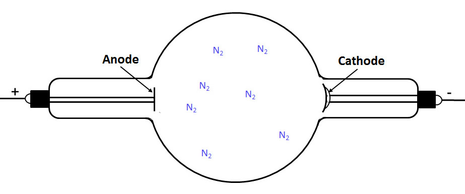
First we see a partially evacuated tube containing residual nitrogen (air) gas molecules:
The next drawing shows that one of these molecules has been ionized by background radiation.
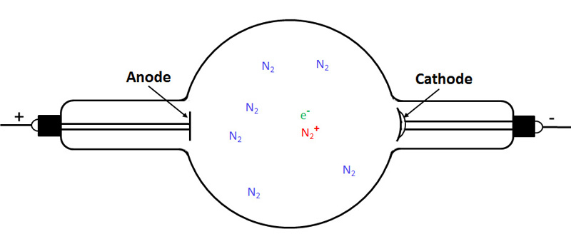
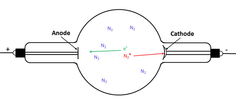
The next figure shows the electron travelling towards the anode and the positively charged nitrogen ion travelling to the cathode.
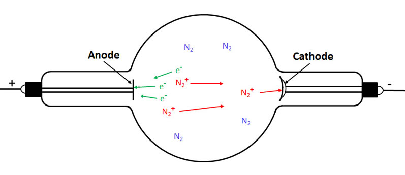
In the following figure we see that the electron travelling to the anode has ionized two more gas molecules. As a result, we now have three electrons (cathode rays) travelling to the anode and three positively charged gas ions (canal rays) travelling to the cathode.
In the final figure, we see an electron being knocked off the cathode where the latter was struck by one of the gas ions.
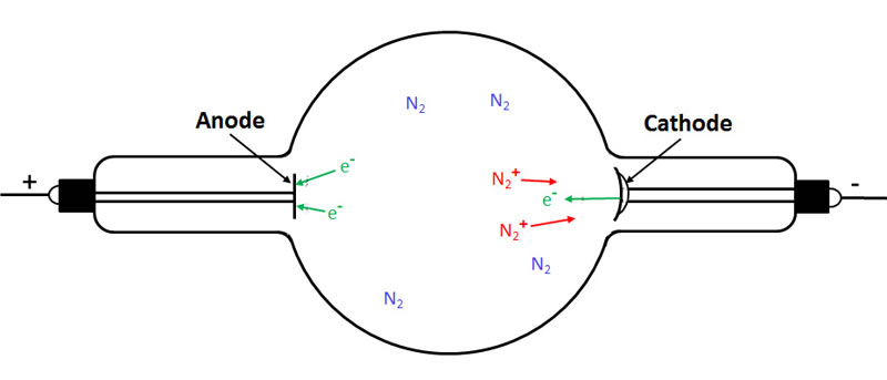
For every electron striking the target, a positive gas ion strikes the cathode.
As long as a high enough potential is maintained between the two electrodes, the cathode ray beam (and canal ray beam) is self-sustaining and the region between the electrodes contains a mix of free electrons, positively charged gas ions, and neutral gas molecules (both excited and unexcited).
The positive gas ions travelling to the cathode are less likely than the electrons travelling to the anode to ionize the gas. However, over time these ions might damage the cathode when they strike it if the tube was operated at high enough currents and voltages. This damage involves "sputtering," a process whereby some of the atoms of a material are knocked free when struck by ions. Electrons striking the target don't have sufficient mass to cause significant sputtering.
As the electrons travel to the anode, they excite, as well as ionize, some of the residual gas molecules. This causes the gas to glow. Ionization and excitation will not occur in the gas close to the cathode because the electrons have not had enough time to gain the required kinetic energy.
Typical Cold Cathode X-Ray Tubes
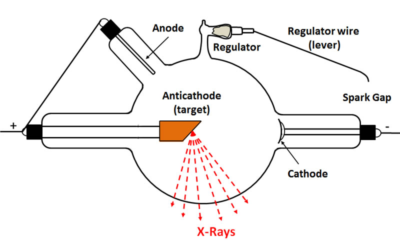
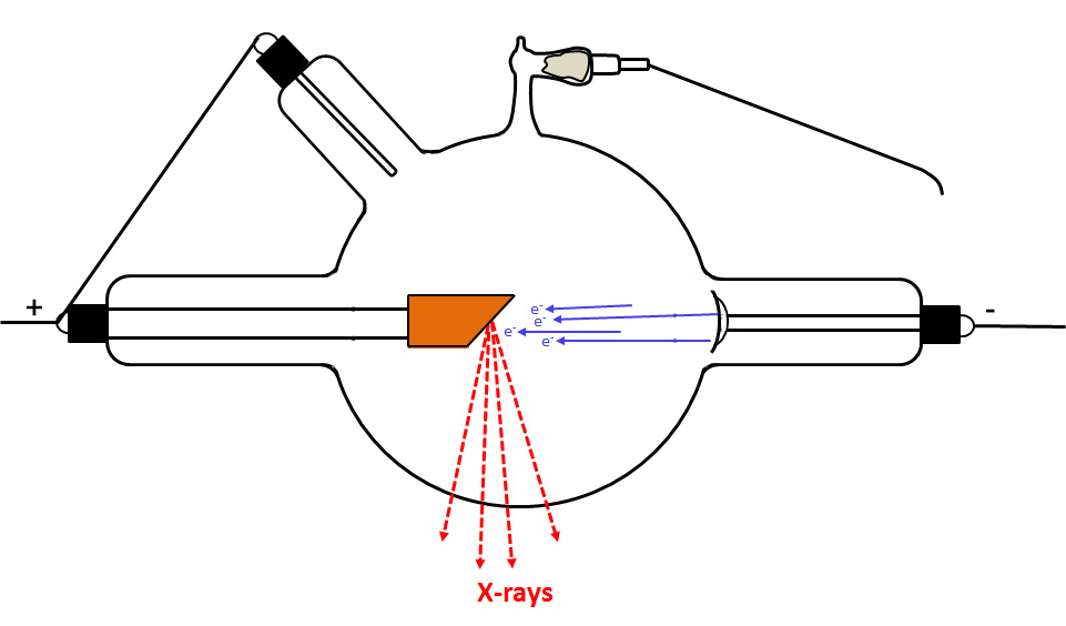
The following diagram illustrates the key components of a typical heavy anode cold cathode X-ray tube.
Cathode
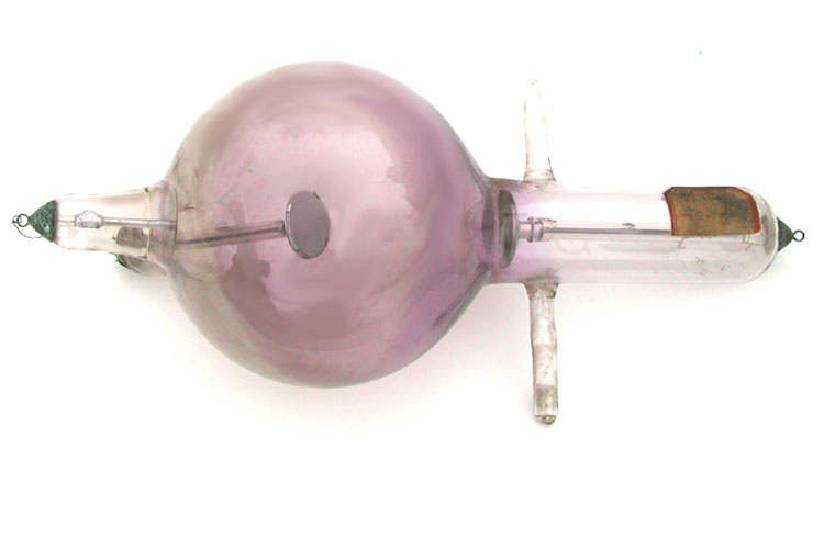
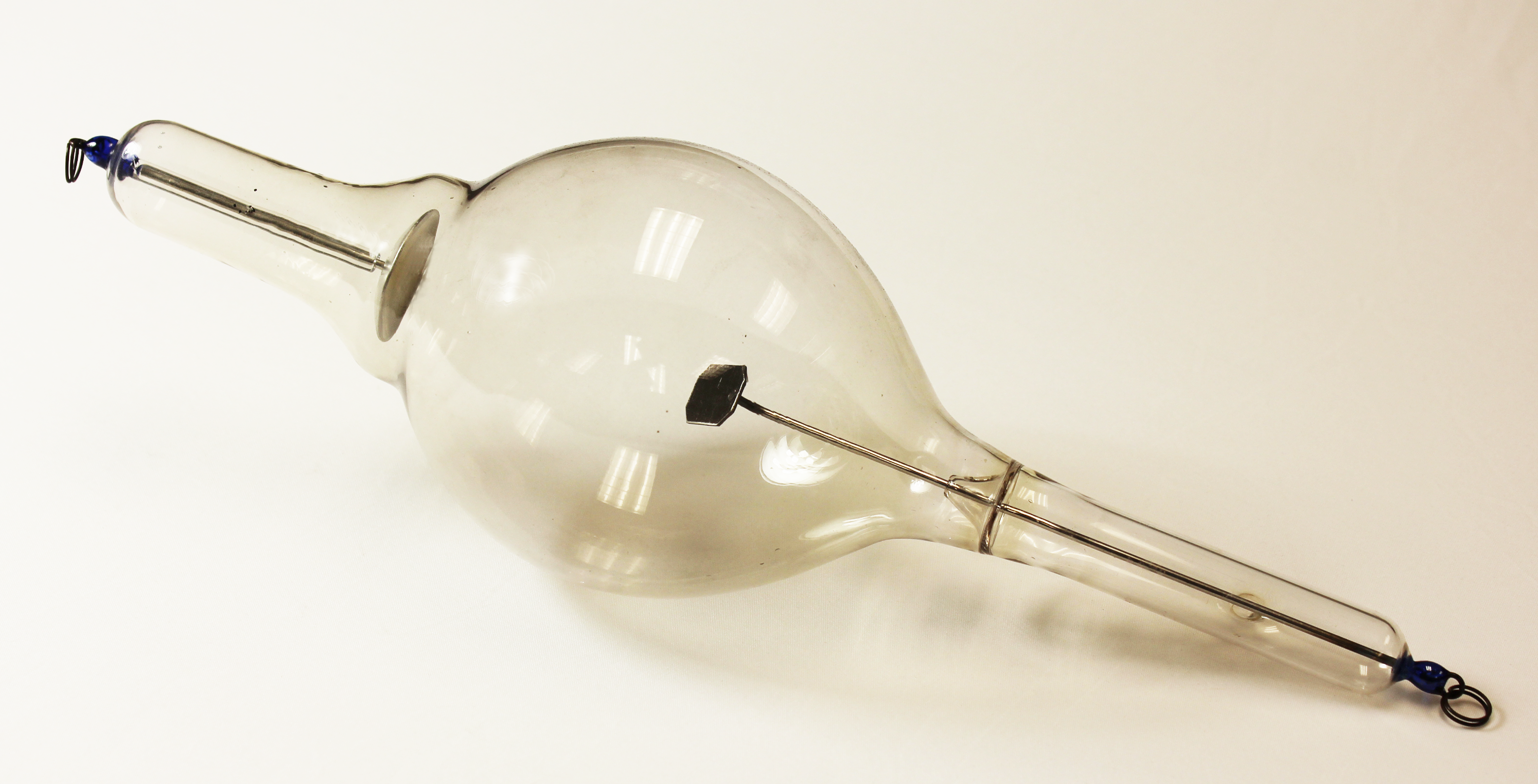
The original cathodes were flat plates that emitted a broad beam of cathode rays (electrons). The resulting X-rays issued from the extended region of the target upon which the cathode rays impinged. Such X-rays produced relatively poor radiographic images. It was soon recognized that better results would be obtained by focusing the cathode rays on a small region of the target. If the resulting X-rays issued form a small point on the target, the images produced by such X-rays would be much sharper. To achieve this, the cathode was curved so that the focal point for the cathode rays was located on the target. For this reason, these tubes were often referred to as "focus tubes" and their cathodes described as "cups." The earliest type of X-ray tube with a focussed cathode was the Jackson tube. Professor H. Jackson of Kings College, London is usually credited to being the first to use a cupped cathode in an X-ray tube. Nevertheless, William Crookes had employed focussed cathodes in his "Crookes tubes" in the days before X-rays were discovered.
The cathode was almost always made of aluminum because aluminum is less prone to "sputtering" than other metals. Sputtering is a volatilization of the metal that occurs when it is struck by gas ions. The volatilized metal, which deposits on the glass walls of the tube, has a tendency to absorb some of the gas in the tube. This increases the tube's resistance to the flow of current and ultimately shortens its life. If sufficient metal deposits on the tube's glass walls, the latter might darken. In general, a visibly darkened tube is likely to have too high a vacuum (too low a gas pressure) to be usable.
In almost all cold cathode X-ray tubes, the cathode cup (aka mirror) is positioned near the circumference of the spherical bulb portion of the tube. Unfortunately, I have never seen the reason for this clearly explained. The position of the cup along along the glass arm that leads to the bulb certainly affects the voltage required to generate a given intensity of X-rays: the farther along the glass arm (i.e., the closer to the bulb) the lower the required operating voltage and the lower the energy of the X-rays produced. The reason, as Hittorf noted, is that a static charge will accumulate on glass (e.g., the glass arm) located near an electrode. The greater this charge, and proximity of the glass to the electrode, the more resistant the electrode becomes to the emission of electrons.
Perhaps positioning it on the bulb's circumference results in the optimal combination of high voltage, X-ray intensity and X-ray energy. Perhaps.
Anode
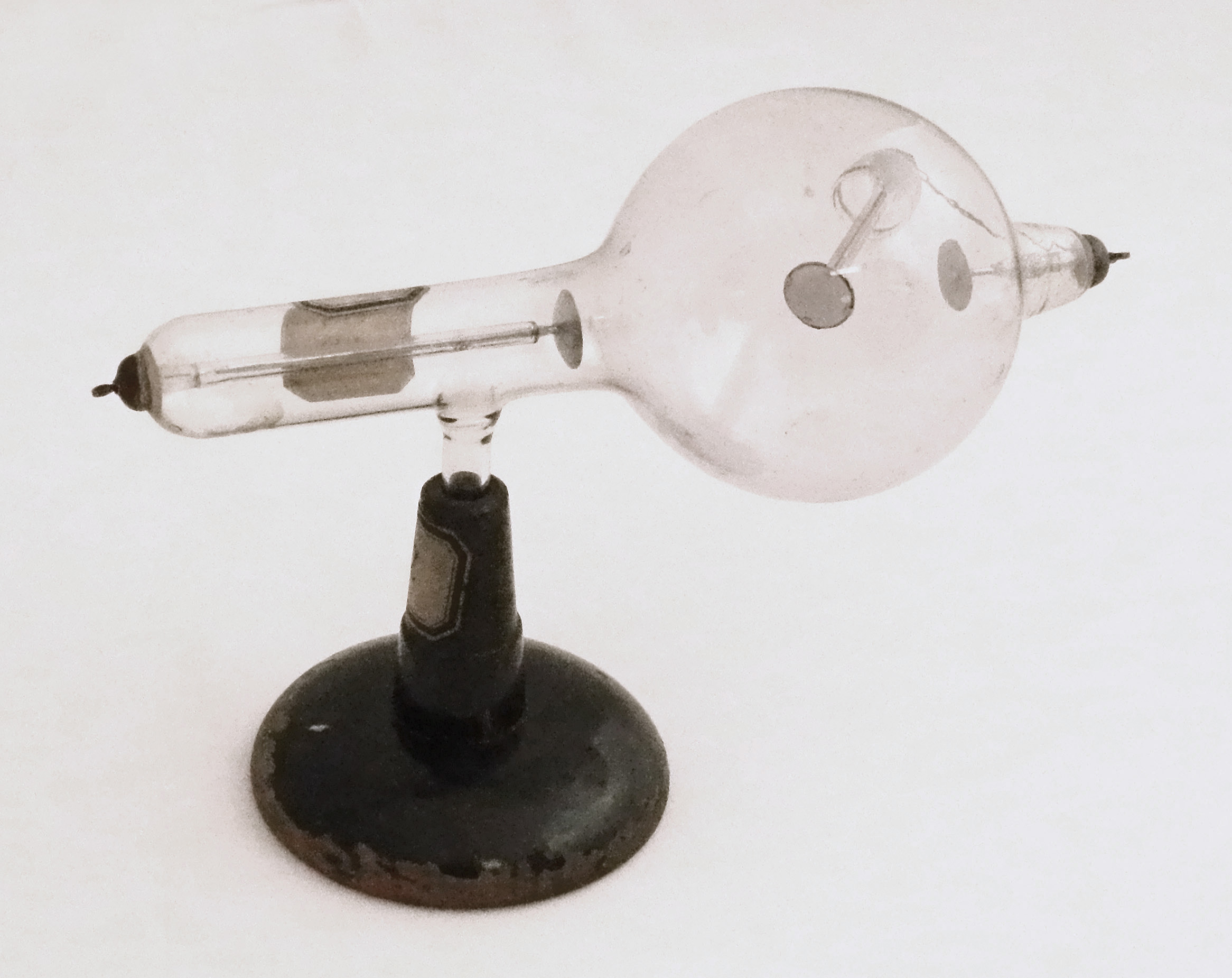
In many of the earliest tubes employed for X-ray production (e.g., Crookes and Hittorf tubes), the anode was located off to the side at one end of the tube. The cathode rays streamed past the anode and struck the glass end of the tube which served as the source of the X-rays. Unfortunately, the glass could not hold up under prolonged use. Furthermore, the X-rays were of low intensity. One early solution was to position the anode (a flat metal plate) at the far end of the tube opposite the cathode. In this configuration, the anode served as the target of the cathode rays and the source of the X-rays.
Anticathode
Most of the early X-ray tubes were what was known as bi-anode tubes, i.e., they had two anodes: the anode proper and an auxiliary anode known as the "anticathode."
The term "anticathode" was coined by Silvanus Thompson to refer to the target upon which the cathode rays (electrons) impinged. Sometimes the anode and anticathode were one and the same, but in most of the early tubes they were distinct entities. In most cases the anticathode was electrically connected to the anode so that both possessed a positive charge. In some cases, the operator might disconnect the anticathode in an attempt to improve tube performance.
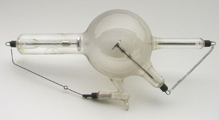
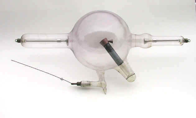
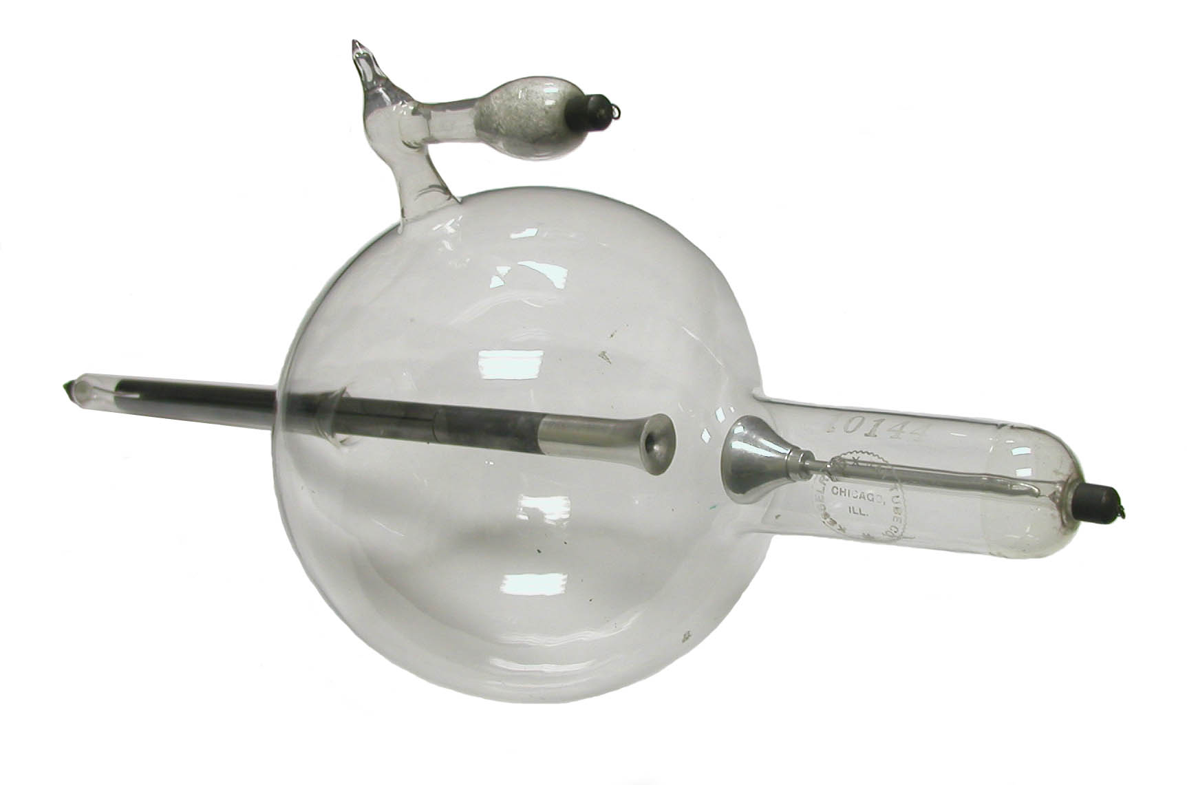
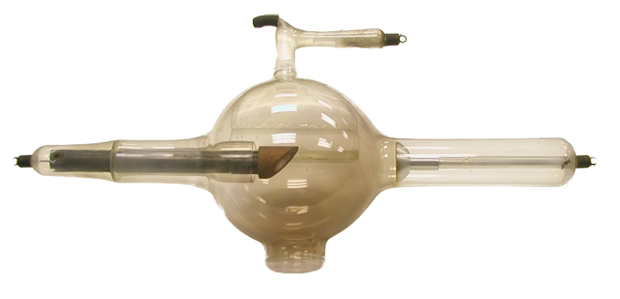
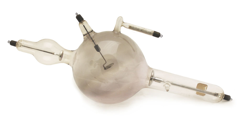
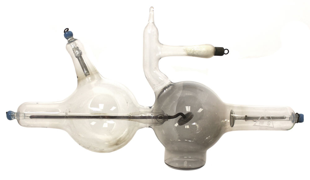
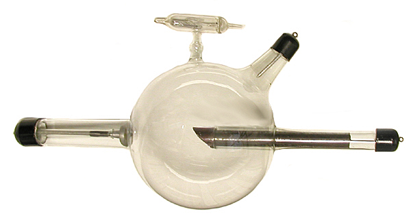
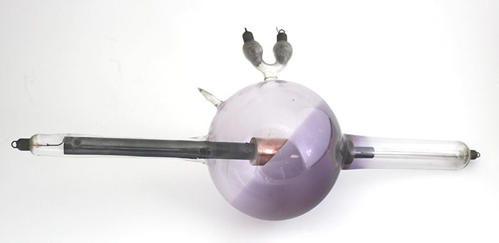
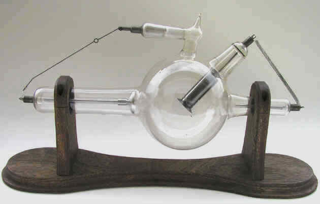
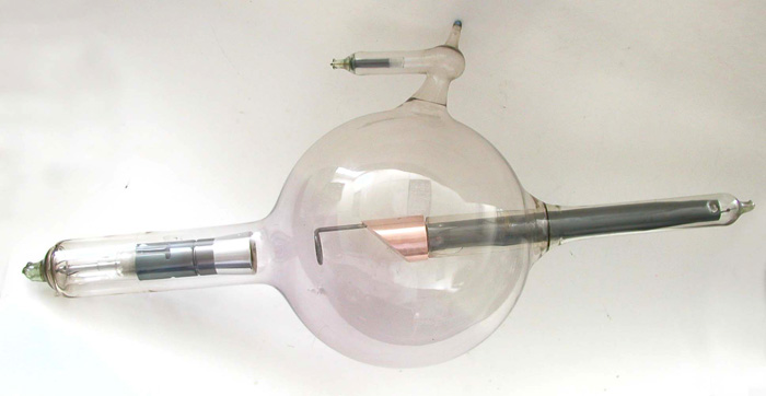
In many tubes, the supporting arm for the anticathode came in from the side of the tube at a 45 degree angle and the anode was located along the tube axis. In other cases, the anticathode was positioned along the tube axis and the anode entered the tube at a 45 degree angle—from above and behind the target as seen in the above figure.
The earliest anticathodes were thin and flat metal (e.g., platinum) plates oriented at a 45 degree angle to the tube axis, but these were prone to overheating under prolonged or intense use. Where this was an issue, more massive "heavy" targets were used to facilitate heat dissipation. For some reason, they were referred to as "heavy anodes" rather than "heavy anticathodes" or "heavy targets." Anyway, these "heavy anodes" or targets generally consisted of two different types of metals bonded together. A metal with a high atomic number (e.g., platinum, osmium, molybdenum, tungsten) served as the actual target for the cathode rays and the source of X-rays, while the surrounding metal (always copper) helped dissipate the heat.
There was no clear understanding as to why it was useful to have an anticathode (target) in addition to the separate anode. The general assumption was that having both prolonged the life of the tube and/or reduced undesirable variations in the gas pressure. Even though some manufactures believed that eliminating the anticathode was just fine, they still produced tubes with separate anodes and anticathodes because their customers expected it. Eventually (ca. 1920), almost everyone recognized that employing both an anode and anticathode served no useful purpose. As a result, late model tubes eliminated the anticathode and positioned the anode on the long axis of the tube opposite the cathode. But by this time, cold cathode tubes had been made obsolete by General Electric’s hot cathode high vacuum Coolidge tube. That tube signaled the end of an era, and the beginning of a new one.
The Importance of the Gas Pressure
For proper operation of the tube, the pressure of the residual gas inside the tube needed to be on the order of 0.2 to 0.5 mm Hg. A tube with higher pressures (a low vacuum) was too "soft," while a tube with a lower pressure (high vacuum) was too "hard."
The X-rays emitted by softer tubes were more intense but of lower energy than those emitted by harder tubes. As a rule, the more intense and lower energy X-rays emitted by soft tubes were desired for therapy—these lower energy X-rays were more likely to be absorbed by the malignant tissue being treated. For diagnostic imaging (radiography), the higher energy X-rays emitted by harder tubes were preferred for their penetrating power. The greater the thickness of the tissue being imaged, the higher the X-ray energy desired. Most physicians would maintain a variety of X-ray tubes, the softer tubes for therapy and the harder tubes for imaging.
Unfortunately, a tube's internal gas pressure was not constant.
Over time, the long-term trend was for the gas pressure to decrease (an increasing vacuum) as some of the gas was adsorbed by the tube’s walls and other components. This inevitable long-term hardening of the tube reduced the intensity of the X-rays. At the same time, the X-rays became more penetrating (higher energy). If the tube became too hard, arcing might occur when power was supplied and the resulting sparks might puncture the tube's glass wall.
Short-term variability could also occur. For example, as a tube warmed up during use, the heating might cause an outgassing from some of the tubes metal components (especially the aluminum) and soften the tube—at least temporarily.
A problem: there was no simple way to measure the gas pressure in the tube.
A comparison of "hard" and "soft" tubes is provided in the following table (after Satterlee, 1913).
| Characteristics of Hard and Soft X-Ray Tubes | |
| Hard Tube | Soft Tube |
| Low gas pressure/high vacuum | High gas pressure/low vacuum |
| Lower intensity X-rays due to lower current | Higher intensity X-rays due to higher current |
| Higher energy (more penetrating) X-rays | Lower energy (less penetrating) X-rays |
| Less danger of skin overexposure | Greater danger of overexposure to skin |
| Less contrast in radiograph | More contrast in radiographic image |
| Electrical charge (static) on outside of tube | No static charge on outside of tube |
| Glass wall of tube more likely to puncture | Glass wall of tube less likely to puncture |
| Surface of target less likely to be damaged | Target more likely to be damaged |
| Yellowish color. | Blue-green colors. Red if extremely high pressure (tube puncture?) |
One method that was used to help maintain a more constant pressure in the tube was to make it larger. The physically bigger the tube, the slower the decrease or increase in the gas pressure. As a result, there was also a relationship between the tube size and its maximum load. The larger the diameter of the tube, the greater the current and high voltage that it could tolerate. The downside of making the tube larger was that it was also necessary to make the glass thicker and this reduced the emission of low energy X-rays. If the latter were needed (e.g., superficial therapy), the tube was small.
Eyeballing the Tube's Performance
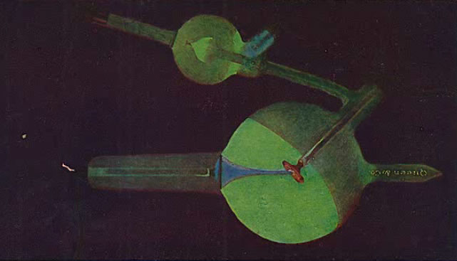
To some extent, it was possible to assess the tube performance by observing it in the dark while it was operating. What the operator might look for would be the color (as well as the pattern) of the light being emitted by the tube's gas when interacting with the X-rays, the color of the gas between the cathode and target where the cathode ray beam was located, and the colors of the target and cathode. Of particular concern would be any observed static discharges on the outside surface of the tube.
With a properly operating tube, the glass should glow (due to excitation by the X-rays) an apple green. Furthermore, this glow should occur in what is known as the anterior hemisphere of the bulb, i.e., the hemisphere subtended by the plane of the target from which the X-rays are emitted. The boundary between the glowing anterior hemisphere and the dark posterior hemisphere should be sharp. This is illustrated below (from Kasabian 1907).
The following figure (from Kasabian 1907) shows the appearance of a tube when the current is flowing in the wrong direction: green light is emitted from the posterior hemisphere in a variety of possible patterns. To help identify the direction of current flow and prevent this type of thing, a simple device called an oscilloscope was sometimes inserted in one of the lines between the power source and the tube.
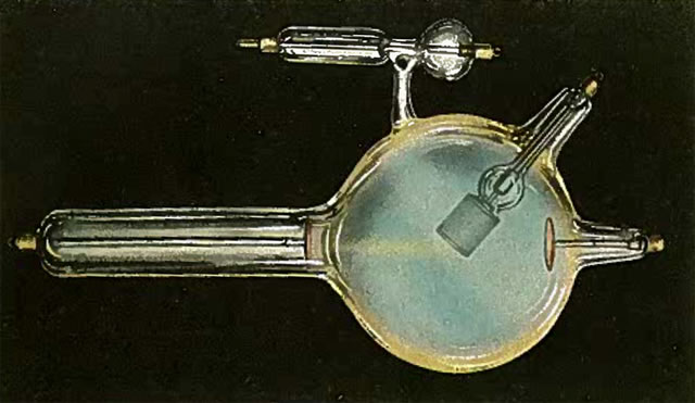
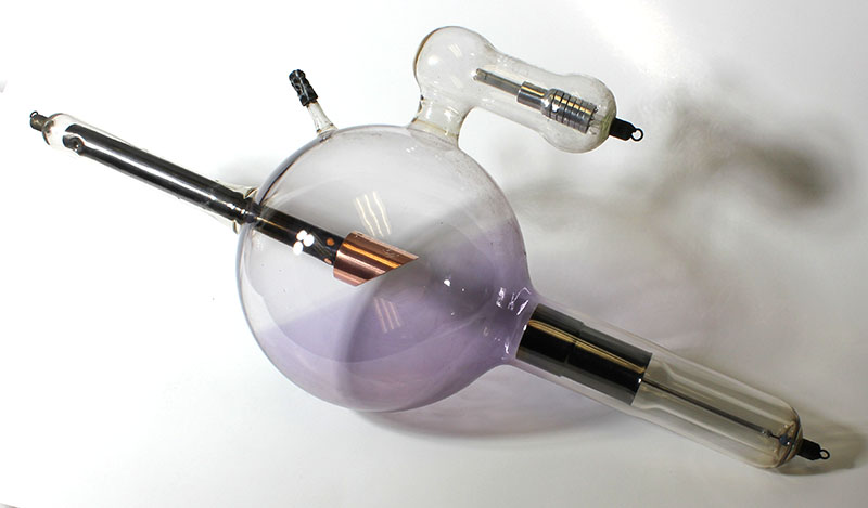
The next two images (the first from Kasabian 1907, the second from Tousey (1916) show the possible appearance of a tube with too low a vacuum (too high a gas pressure), i.e., a soft tube. This is indicated by the presence of a blue or purple color.
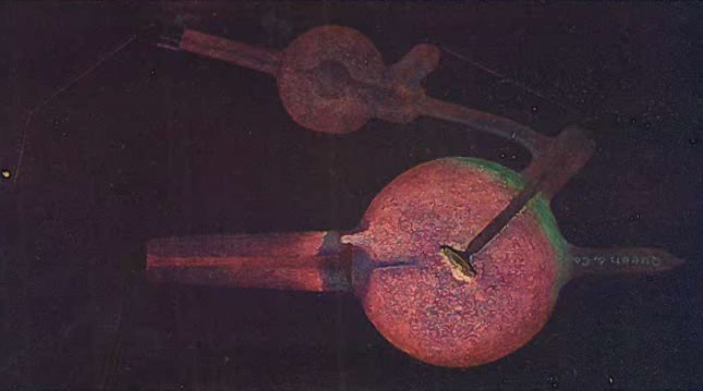
The following image (from Kasabian 1907) shows the appearance of a tube that has been punctured or cracked.
The Glass Bulb
In most situations, the ideal X-ray tube would have a large bulb and thin glass. Unfortunately, the larger the bulb, the thicker the glass has to be in order to prevent the tube from collapsing. The advantage of a larger bulb is that it contains more gas, and the more gas inside the tube, the slower the unwanted but inevitable loss of gas pressure will be. The advantage of using thinner glass is that more of the low energy X-rays will be able to escape the tube. However, not all applications require or desire low energy X-rays.
Adjusting (Regulating) the Tube's Vacuum
The most common problem was softening a tube that had become too hard.
A simple but risky way to increase the gas pressure in too hard a tube was to heat the tube up, either in an oven or directly with a flame. The glass, when hot, would emit a gas and soften the tube. The risk was in breaking the glass in the process. And even when this method worked, the fix was temporary. As soon as the tube cooled, the gas would be reabsorbed by the glass.
A much better approach was to only purchase X-ray tubes that came with a regulator (aka regenerator). There were many variations in the design of these regulators, but fundamentally they were of two different types, each of which will be discussed in some detail.
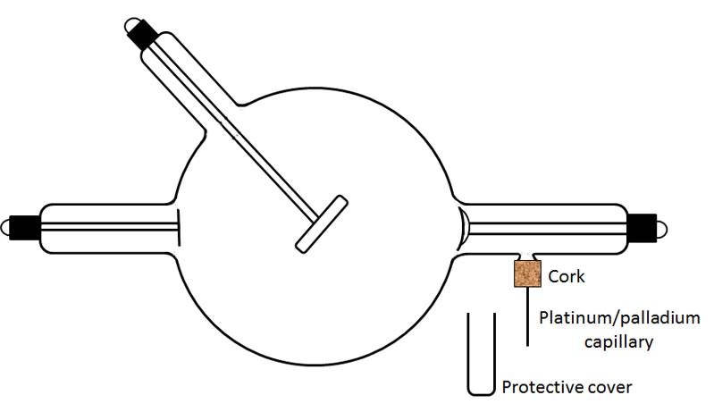
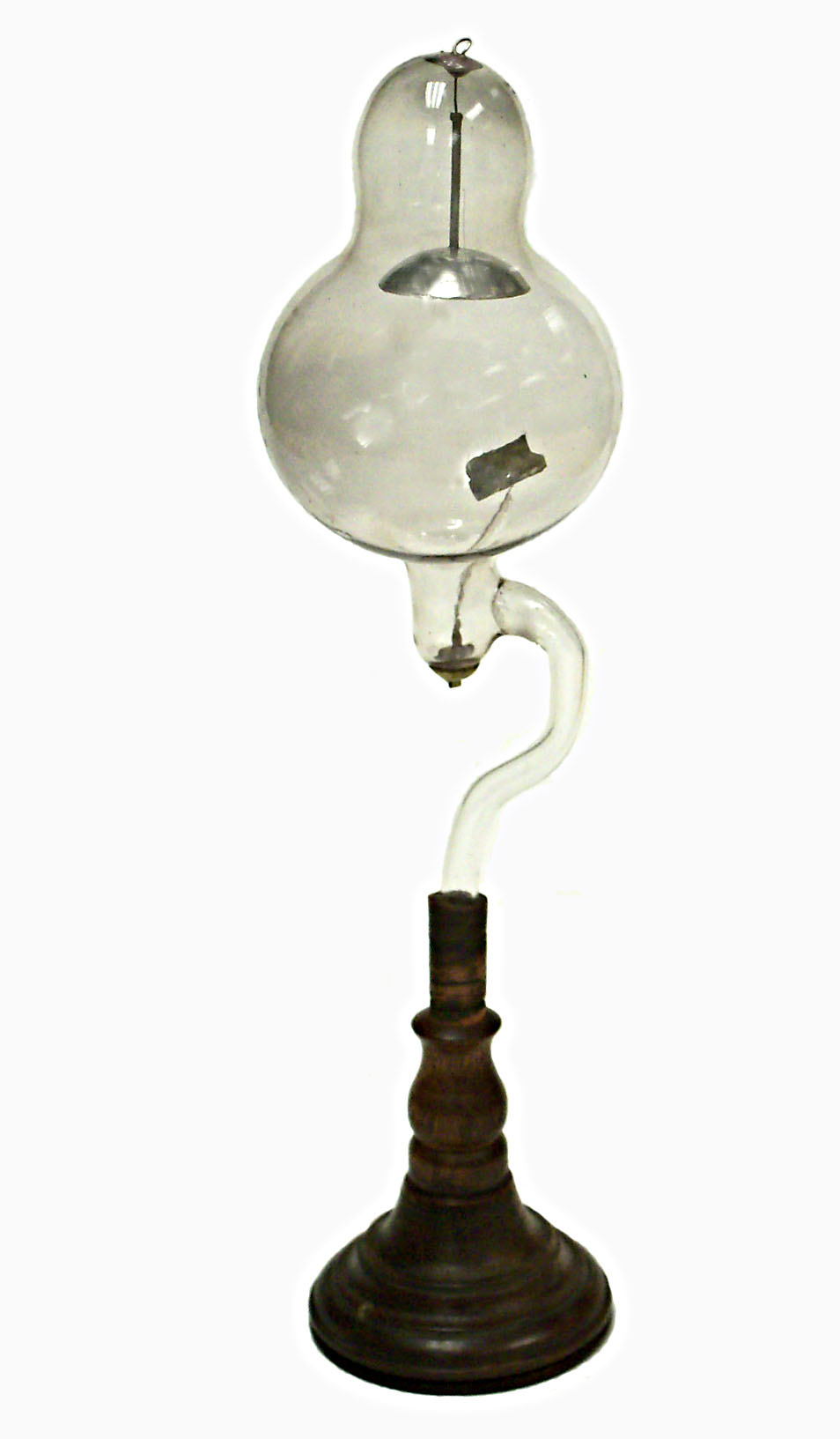
1. The simple and reliable type of regulator, developed by Villard, employed the principle of osmosis. The glass wall of the tube was penetrated by a very fine capillary of platinum or palladium. The end of the capillary outside the tube was sealed, but its other end, the one inside the tube, was open. When the portion of the capillary sticking out of the tube (ca. 1") was heated to a red glow with a flame, hydrogen diffused through the platinum/palladium into the tube and increased the gas pressure. Only a small molecule like hydrogen could diffuse through the metal, and only when the latter was heated. To me, it seems that the movement of the hydrogen into the tube was pressure driven rather than osmosis. The drawing below shows a typical design.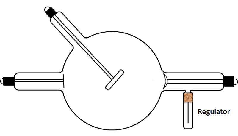
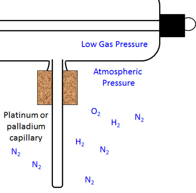
The next figure shows the regulator with its protective glass cover/tube removed.
The figure to the right shows the hollow capillary that serves as the regulator. The ambient atmosphere contained the usual gases, nitrogen, oxygen, etc. Also present are small quantities of hydrogen.
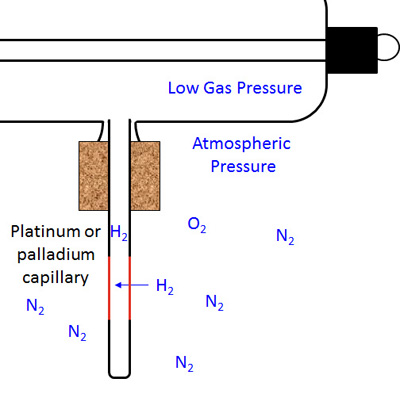
The figure below shows the result of the capillary being heated (note the reddening along part of its length). Only the small hydrogen molecules can diffuse through the capillary wall and enter the tube.
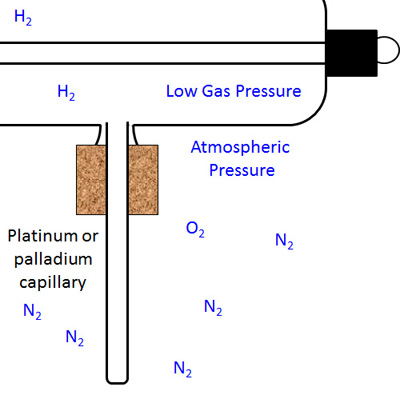
The figure below right shows the situation after the process has been completed and the capillary cooled down. The gas pressure inside the x-ray tube is still low, but not as low as before because of the hydrogen that is now inside.
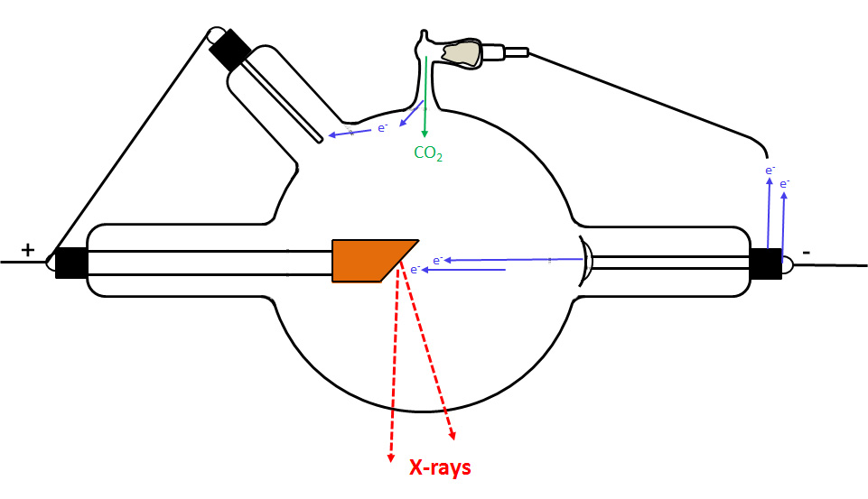
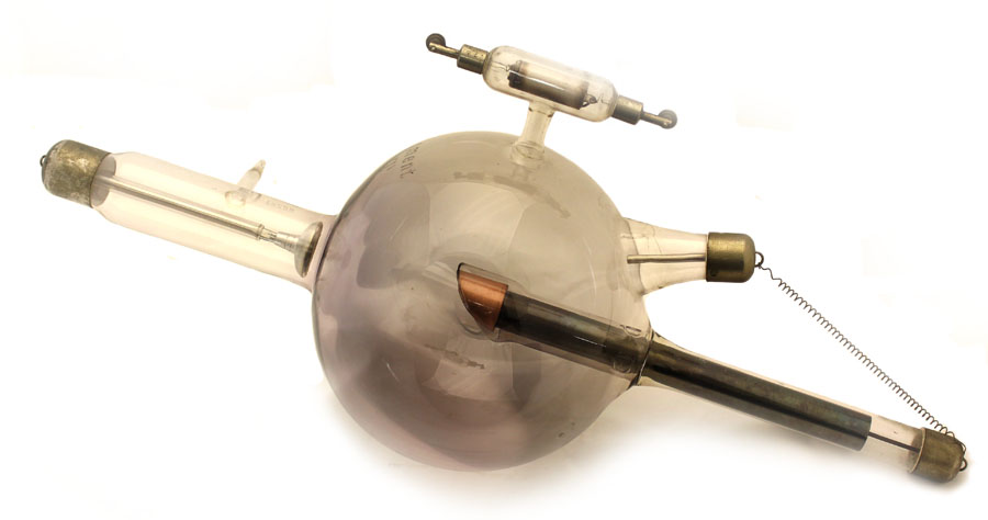
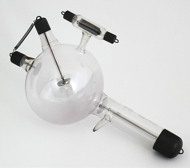
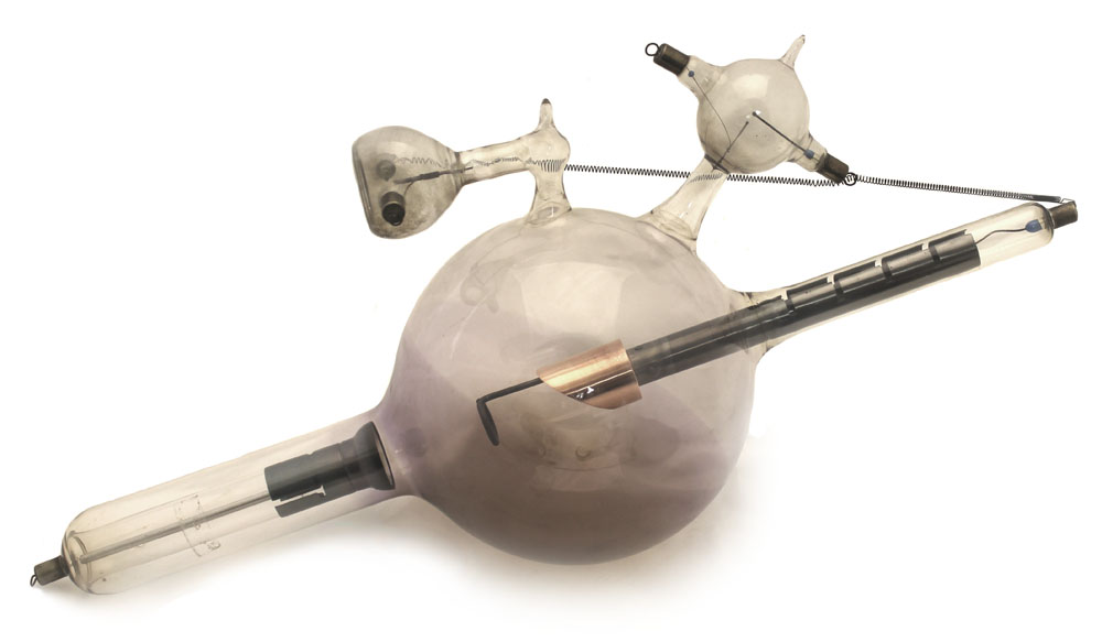
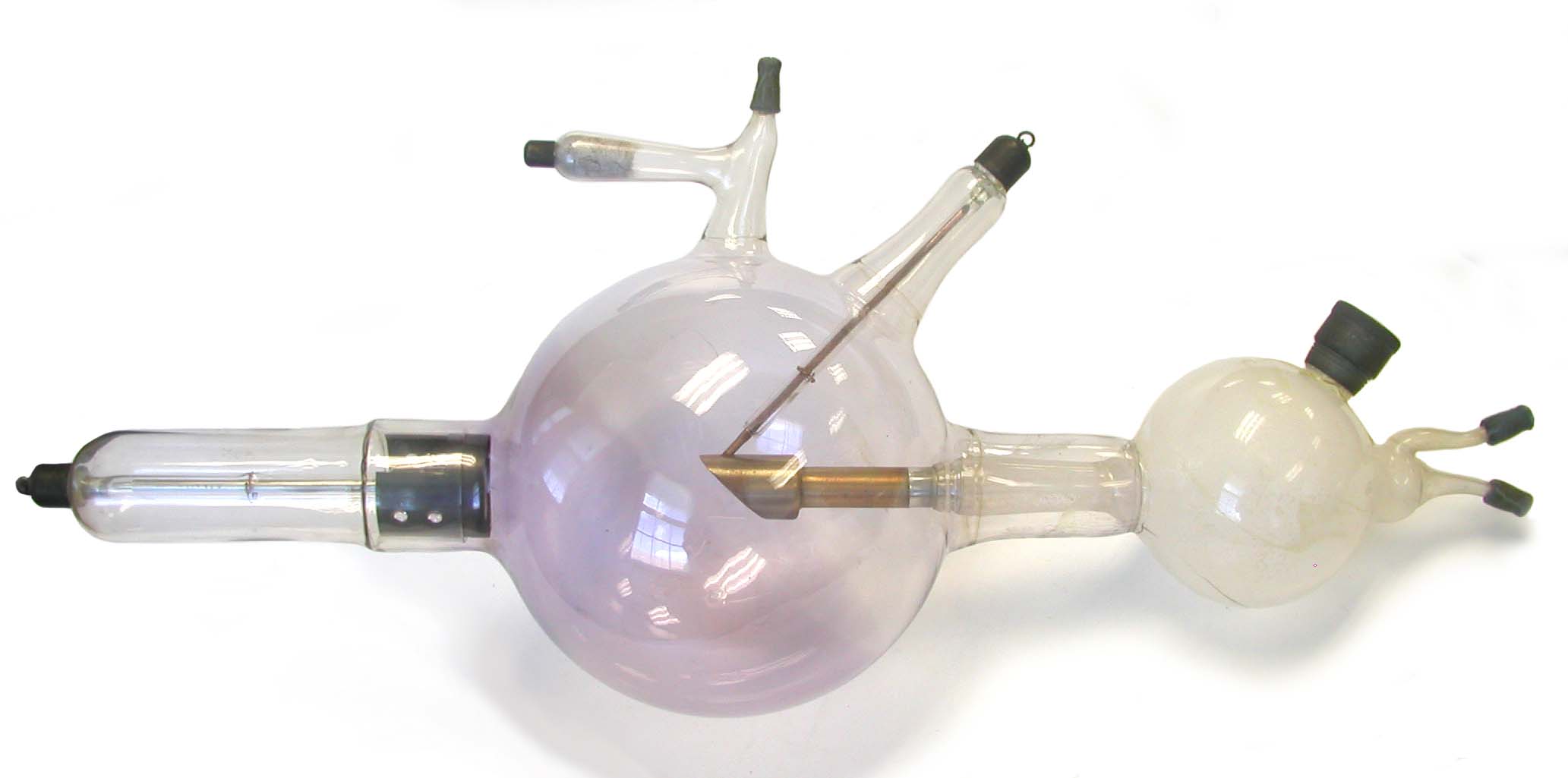
2. The most common type of regulator consisted of a small glass extension to the tube wall. Inside the device was a material that would release a gas (e.g., carbon dioxide) when it was heated or a current was passed through it. This material might be asbestos impregnated with a chemical such as sodium hydrate or potassium hydrate. Potash and charcoal were also used.
In the simplest designs, the regulator was heated directly in a flame.
The more complicated self-regulating systems employed a feedback control. They weren't entirely automatic however, the operator had to adjust and monitor them every time the tube was used.
There was no standard design. The self-regulating regulator might have one or two electrodes. All of them were capable of softening the tube, but some (e.g., the Muller and Snook regulators) were also capable of hardening a tube that was too soft.
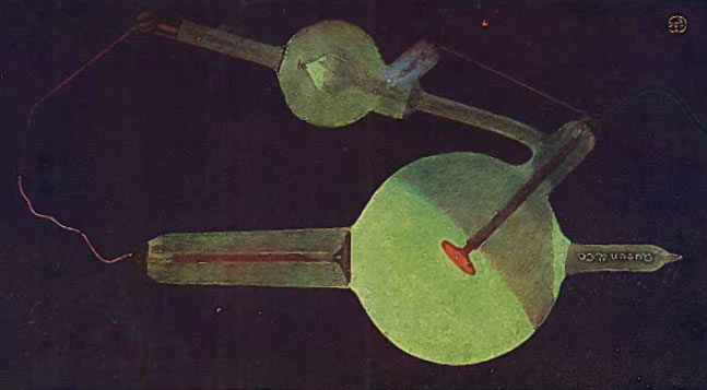
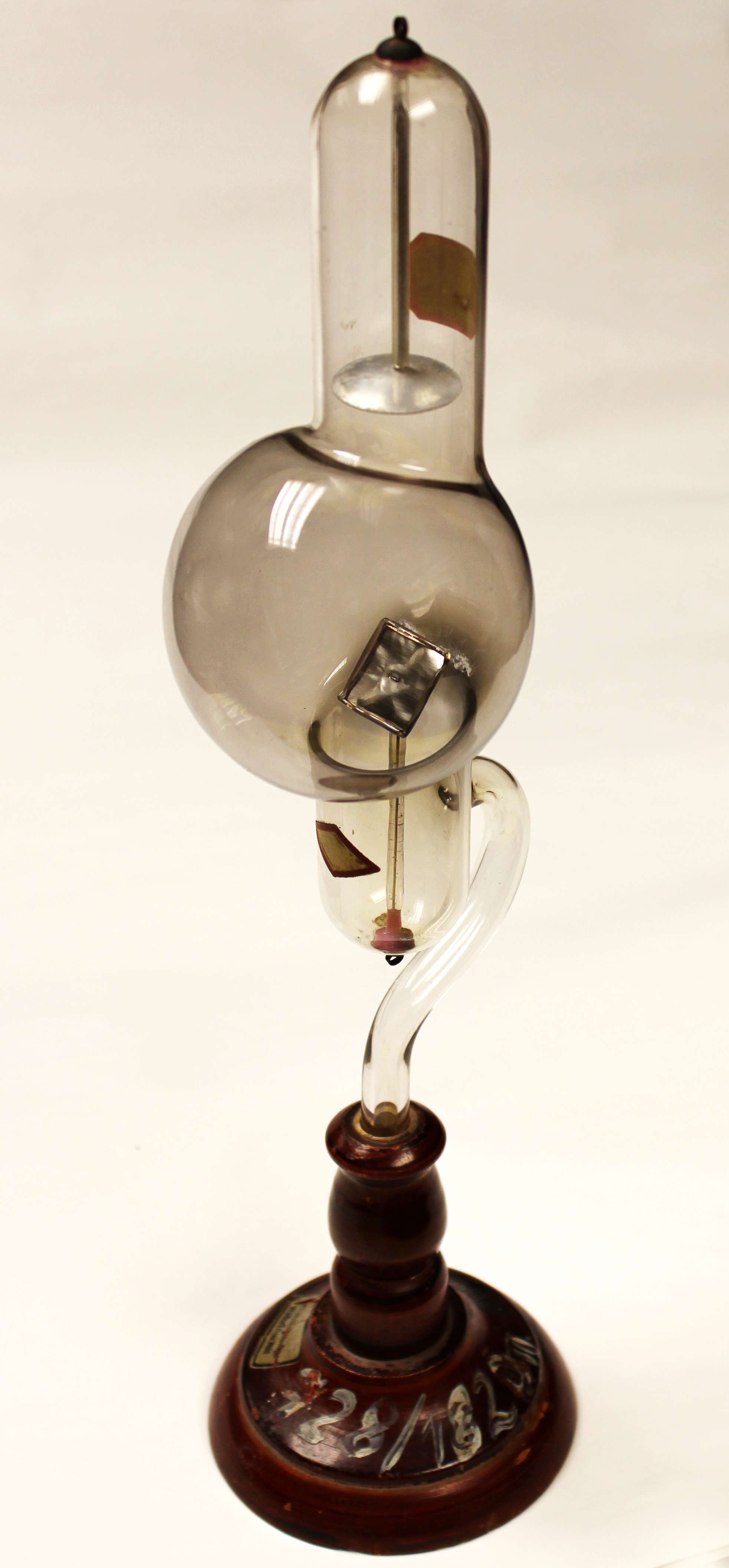
Lets consider the operation of the most basic type of self-regulating tube. This classic regulator design consists of an "L" shaped projection from the main bulb of the tube—it looks a little like a handle on a bathroom sink faucet. Inside the regulator is asbestos in which is mixed a chemical such as sodium hydrate. This regulator has a single electrical terminal which is connected, with a hinge, to a wire lever that can be moved up and down, as needed, by the operator. The free end of the wire is positioned at a specific distance (e.g., 3") from the terminal connection for the tube's cathode.
When a tube gets harder, the flow of current from the cathode to the anode decreases—the lower the pressure (the higher the vacuum) the less conductive the gas. When the resistance to the flow of current from the cathode to the target exceeded a certain point, the current would jump the spark gap between the cathode connection and the tip of the wire lever connected to the regulator. This caused the material in the regulator to heat up and emit a gas which increased the pressure in the X-ray tube. The flow of current through the regulator would cease when the pressure in the tube had been increased to an acceptable level. If a hard tube with more penetrating X-rays was desired, a large gap (e.g., 6") would be used. For a softer tube, a small gap would be employed.
The problem was that the gas released into the tube to increase the pressure would be reabsorbed later when the tube cooled. In other words, it was a temporary fix. This was not the case with osmo-regulators.
In the following image, the gas pressure (vacuum) is fine. The flow of current is exclusively through the tube to the target.
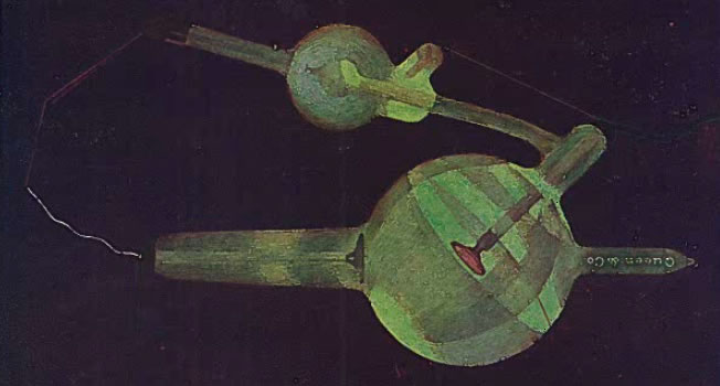
In the next figure, the tube is becoming too hard. In other words, the resistance to the flow of current through the gas is too large because the gas pressure is too low. Some of the current is by-passing the cathode by jumping the spark gap and going through the regulator. As a result, the regulator emits a gas (e.g., carbon dioxide) which increases the pressure in the tube. By this means, the conductivity of the gas keeps increasing until the current stops jumping the spark gap, and instead flows through the tube, the new path of least resistance.
There are too many other types of regulators to describe here, however some of these can be seen on the various tubes in the ORAU collection. Where appropriate, the individual description of a tube includes a discussion of the regulator's mode of operation.
The primary application of the regulator (regenerative device) was to "soften" the tube, i.e., increase the gas pressure in order to make the tube more conductive. However, it is worth noting that certain types of regulators were designed to "harden" the tube (reduce the gas pressure). A device that could do both was variously known as a dual, double or duplex regulator.
Reverse Currents
Needless to say, the current in the tube should flow from the cathode to the target (anticathode). But mistakes happen. What should be the negative terminal of the tube (the cathode connection) might accidently be connected to the positive terminal of the power supply, and what should be the positive terminal of the tube (connections to the anode and anticathode) might be connected to the power supply's negative terminal. A bad mistake, but that is not the real issue.
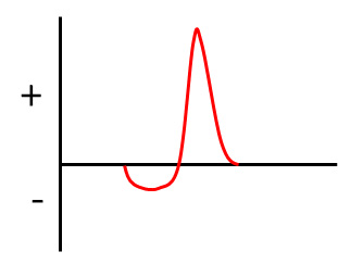
The real problem is this: even when using a battery (or batteries) as the power source, the current supplied to the tube might flow in both directions. The trouble originates with the device being used to step up the voltage, e.g., an induction coil. The latter, for example, cannot increase the high voltage if the current is constant. For it to work, the current supplied to the coil needed to be interrupted, something that could be done mechanically or by some other means. An unfortunate by-product of these interruptions to the flow of current was that the coil's output pulse could have both a negative and positive component.
The figure below shows how the polarity of an output pulse from the coil can change—the reason the current flows in both directions.
Two problems were associated with current travelling (even temporarily) in the wrong direction:
First, sputtering could occur in the wrong half of the cycle when positive gas ions struck what was normally the target. The latter was made of a metal (e.g., platinum, tungsten) that was more prone to sputtering than the aluminum cathode, and this sputtering caused the tube to harden more rapidly than it should.
Second, during the wrong half of the cycle when the current travelled in the wrong direction, X-rays would be generated at the tube's cathode where it was struck by electrons. Since the X-rays were now being emitted from multiple points in the tube, any radiographic images being produced would be blurred. Of course, this was less of an issue in therapy than in imaging.
Various things, not all of which worked, were tried in an attempt to mitigate this reversed flow of current:
A valve tube (or tubes) might be placed in the electrical circuit between the power source and the tube. For an example, check out the Kesselring Valve tube.
The target (anticathode) might be partially surrounded by a glass mantle. This was believed to suppress the emission of electrons from the target during the wrong half of the cycle. For an example, take a look at the Gundelach "Moment" X-ray tube.
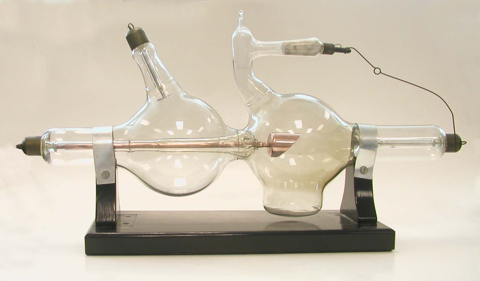
A copper funnel might be attached to the back of the target with the funnel opening pointing towards the anode. The collection's Kesselring High Frequency tube has one of these.
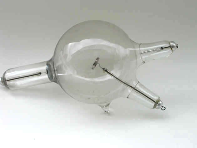
A "focussing ring," supported by a rod extending from the target, might be positioned approximately half-way between the target and cathode. To see such a ring, take a look at the Snook X-ray tube.
A bi-anode X-ray tube might employ an aluminum anode. Heck, almost all bi-anode tubes did. During periods of reversed current, many of the positive ions produced in the gas would be collected at the anode. Since the anode was made of aluminum, sputtering would not occur when it was struck by these ions.
Static Discharges on the Tube Surface
Under certain conditions, sufficient static charges could build up on the outside of the tube for arcing to occur. As a related matter, it was sometimes the case that a portion of the current might bypass the tube and travel over the surface of the glass from the negative (cathode) terminal to the positive (anode, anticathode) terminal. One unwanted result might be an electrical discharge that punctured the tube and resulted in a loss of vacuum, something not necessarily obvious to the operator. Similar static discharges could damage the tube even when the latter was placed on a rack for storage!
Minimizing the potential (pun intended) for damaging electrical discharges involved;
Avoiding unnecessarily high voltages when operating the tube.
Grounding all equipment.
Employing longer tubes that maximized the distance between the electrical terminals of the cathode and anticathode (or anode).
Keeping the electrical lines well separated from each other.
Finally, we shouldn't forget the possibility of death due to electrocution.
References
- Kasabian, M.K. Rontgen Rays and Electro-Therapeutics. 1907.
- Ronne, P., Nielsen, A.B.W. Development of the Ion X-ray Tube. 1986.
- Satterlee, F.R.L. Dental Radiology. 1910.
- Tousey, S. Medical Electricity, Rontgen Rays and Radium. 1916.
"After Roentgen" - Tubes Designed to Produce X-Rays
-
Aetna Electric Co. X-Ray Tube Aetna Electric Co. X-Ray Tube
-
Air-Cooled X-Ray Tube Air-Cooled X-Ray Tube
-
Bellevue Interrupterless Transformer Tube Bellevue Interrupterless Transformer Tube
-
Cancer Treatment X-Ray Tube Cancer Treatment X-Ray Tube
-
Cold Cathode X-Ray Tube Cold Cathode X-Ray Tube
-
Early Kesselring Cold Cathode Tube Early Kesselring Cold Cathode Tube
-
Gundelach "Moment" X-Ray Tube Gundelach "Moment" X-Ray Tube
-
Gundelach Light Anode Tube Gundelach Light Anode Tube
-
Gundelach Light Anode Tube Gundelach Light Anode Tube
-
Jackson X-Ray Tube Jackson X-Ray Tube
-
Kesselring High Frequency Tube Kesselring High Frequency Tube
-
Kesselring Valve Tube Kesselring Valve Tube
-
Kny-Scheerer (Kayess) Tube Kny-Scheerer (Kayess) Tube
-
Macalaster & Wiggin Cold Cathode X-Ray Tube Macalaster & Wiggin Cold Cathode X-Ray Tube
-
NitroKen Tube NitroKen Tube
-
Piffard Safety X-Ray Tube with Heavy Anode Piffard Safety X-Ray Tube with Heavy Anode
-
Piffard Safety X-Ray Tube with Light Anode Piffard Safety X-Ray Tube with Light Anode
-
Pregnant Jackson X-Ray Tube Pregnant Jackson X-Ray Tube
-
Pressler (possibly Schilling) Cold Cathode X-Ray Tube Pressler (possibly Schilling) Cold Cathode X-Ray Tube
-
Pressler Cold Cathode X-Ray Tubes Pressler Cold Cathode X-Ray Tubes
-
Queen Self-Regulating Tube Queen Self-Regulating Tube
-
Simple Cold Cathode X-Ray Tube Simple Cold Cathode X-Ray Tube
-
Swett & Lewis Type W Tube Swett & Lewis Type W Tube
-
The Snook Hydrogen Tube The Snook Hydrogen Tube
-
Tube with Bauer Regulator Tube with Bauer Regulator
-
Tube with U-shaped Regulator Tube with U-shaped Regulator
-
Victor Cold Cathode X-Ray Tube Victor Cold Cathode X-Ray Tube
-
Victor X-Ray Tube with Focusing Ring Victor X-Ray Tube with Focusing Ring
-
Water-cooled X-Ray Tube of Unknown Manufacture Water-cooled X-Ray Tube of Unknown Manufacture
"Before Roentgen" - Tubes not Designed to Produce X-Rays
-
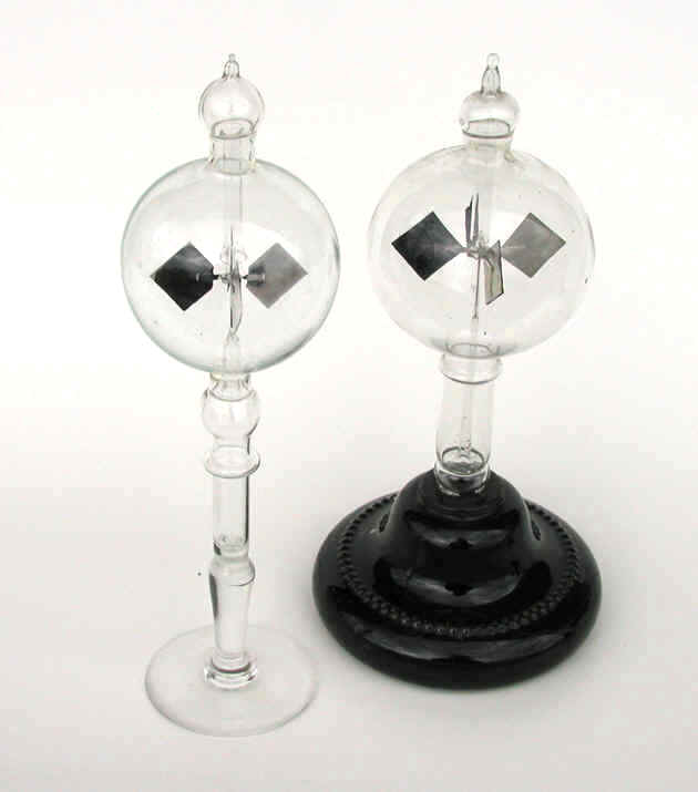
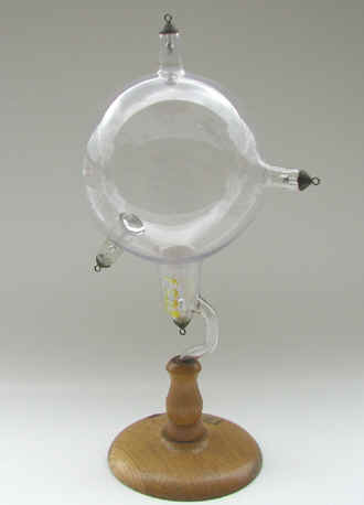
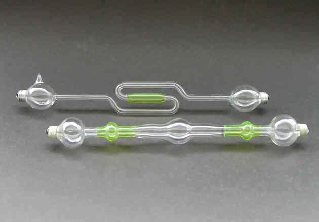
Crookes Radiometers Crookes Radiometers
-
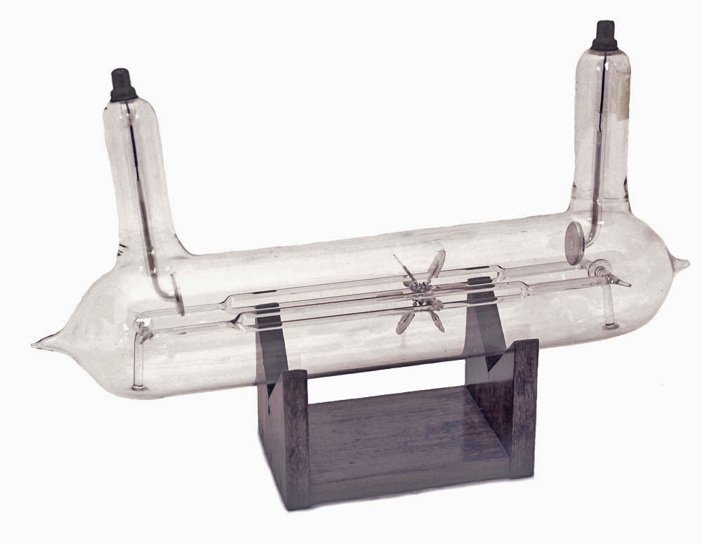
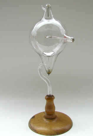
Crookes Railway Tube Crookes Railway Tube
-
Crookes Tube Crookes Tube
-
Crookes Tube With Three Anodes Crookes Tube With Three Anodes
-
Geissler Tubes Geissler Tubes
-
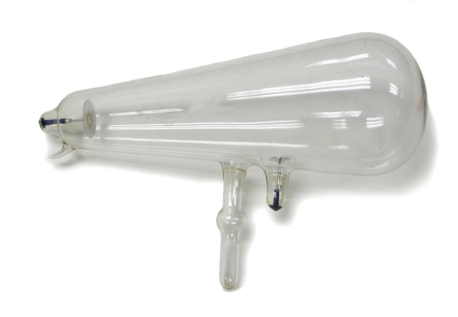
Heating Effects Tube Heating Effects Tube
-
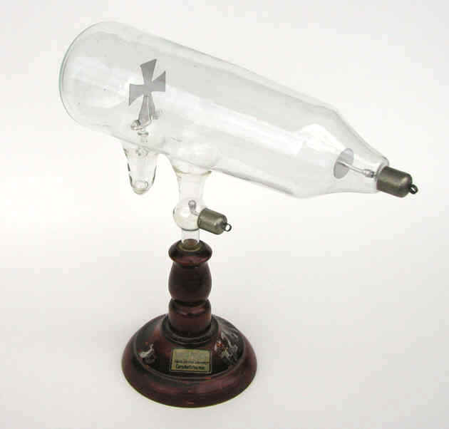
Maltese Cross Crookes Tube Maltese Cross Crookes Tube
Radiation Tubes - Part 1
Some of the real treasures of the ORAU Health Physics Historical Instrumentation Collection are the radiation and X-ray tubes, some of which are over 100 years old. In this video, Dr. Paul Frame shares his wealth of knowledge about some of the tubes he has collected over the last 36 years.
Radiation Tubes - Part 2
The collection includes a number of radiation tubes, along with mechanisms to measure the radiation output of the tubes.